We want to address something that’s coming up frequently in the modding community… that the first impression of backlighting a Game Boy Pocket is disappointing. We get it. It doesn’t have to be, though, as the primary issue is brightness of the backlight - or sometimes the system simply behaving oddly or failing to stay powered-up.
Here’s the good news: this is an easily resolved problem… it may seem intimidating at first, but the solution is a 5V step-up (aka ‘boost’) voltage regulator. I’m going to cover not only the solution, but we’ll dive a bit into what’s happening and why the backlight is dim (or the system failing to work at all).
What’s going on here?
Simply enough the Pocket is awesome in that it’s very small, light, and is even powered by just 2 AAA batteries… and at the same time the issue is that, electrically speaking, it runs on very thin margins. Simply enough the main DC-DC convertor in the Pocket was designed to handle the system itself and using standard cartridges... there isn't enough margin for things like a hungry backlight and/or flash cartridge. While 2 AAA batteries add up to ~3.0v (alkaline), keep in mind that the system itself is using the bulk of that the batteries don't spend much time at the full 3.0v, either. The backlight is dim due to not getting sufficient voltage. Sometimes even, as mentioned, the system will behave oddly, visual anomalies, or even fail to stay powered-up at all… that depends on a number of factors, which I’ll skip for now to get at the solution.
Ok, so now what?
What’s needed is to boost the voltage supplied to the backlight, which is aptly named since the common name for the part is a 5V ‘boost’ [voltage] regulator… more formally known as a 5V step-up [voltage] regulator. These are rather small PCBs (Printed Circuit Boards) but very important in function.
A 5V step-up regulator (I’ll call it a ‘boost’ going forward) does exactly what it says it does in that it takes voltage as low as 0.5V (per spec of our suggested boost) and ‘steps it up’ to a smooth and continuous 5V.

You can purchase the Polou U1V10F5 on their site currently for $4.49 USD (for 1) plus shipping: https://www.pololu.com/product/2115. You’ll need one to do this mod. Mind you this isn’t the only boost that will work, I simply find it to be the smallest and easiest to tuck away in consoles.
Installation
What’s we’re going to do is get the boost installed in a way that uses essentially straight battery power so that it does two things:
- Won’t strain the stock DC-DC regulator, which at 23 years old is likely showing its age.
- Providing the backlight its needed steady 5V power supply.
Required
- Soldering iron and supplies
- Multimeter
- Wire (30 gauge suggested)
- Game Boy Pocket prepped for backlighting
- Backlight
- Resistor (if the backlight doesn’t have one built-in) It's very important to ensure you have the right resistor for the color of backlight you're installing!
Installation (presumes console open, etc)
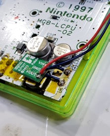
Note: We’ll be placing the boost on the back of the speaker, so be sure to give yourself enough wire to do that.
- Start by soldering VCC from the Pocket’s regulator (middle-left solder point) to VIN on the boost.
- Solder GND from the Pocket’s regulator (lower-left solder point) to GND on the boost.

- Check for continuity, while the console is off - you want to ensure you have a good connection between VCC and VI, and between GND and GND. You do not want continuity between VCC and GND… if your meter gives a positive continuity indication (usually a beep/tone), then you’ve got a solder bridge and need to correct that before proceeding.
- Power on the console, and use your multimeter to measure the output of the boost between GND and VO, looking for a steady 5V (I usually see ~5.15V). If that looks solid and steady, power down the console lets move on.
- If your backlight does not have a built-in resistor, you’ll need the correct resistor for your color of backlight - check with the vendor if you're unsure. Solder the backlight POS (+, red) wire to VO on the boost… wire-in the resistor if needed. Note: Our Hand Held Legend V3 backlights have the resistor built-in; no external resistor is needed.
- Solder the GND (-, black) wire from the backlight to GND on the boost… you might have to re-solder this to ensure that both GND from the Pocket and GND from the backlight are soldered to this same GND point on the boost.
- Check for continuity again - you want continuity between POS (+, red) on the backlight and VOUT on the boost. You’ll also want continuity between GND (-, black) on the backlight and GND on the boost. Be sure to test for continuity between GND and VOUT - if you get a positive indication, you’ll need to correct that (usually a solder bridge) before proceeding.
- Power on the console - the backlight will power-on at this point and be at it’s full brightness, with the console doing it’s normal power-on procedure.

You’re all set regarding the backlight… now where to put this stuff? As mentioned briefly ahead of the wiring instructions, we’re going to place the boost on the back of the speaker - there’s a bit of room there, and the step-up is small, so it works out well. If you’ve placed your bivert module there, you can pick up our Pocket Bivert (link below) or relocate the bivert or the 5v step-up to another location in the Pocket (something not covered here, for brevity and focus).

Suggested: Recap
Especially if your console had difficulty staying powered-up or had other odd behavior when you first had the backlight installed, and to ensure top performance, you’ll want to replace the capacitors in your pocket… there are only four of them, so it’s an easy procedure.
Ok…
Close up the console, now that we’ve tested everything and ensure it’s working, and you’re good-to-go!
Thank you once again, and keep those questions coming! We promise to do what we can to answer the most common questions to the best we’re able.
Product mentions
- Console5 cap-kit for Game Boy Pocket (https://console5.com/store/game-boy-pocket-smd-cap-kit-gbc.html)
- Hand Held Legend Pocket Bivert (https://handheldlegend.com/collections/frontpage/products/game-boy-pocket-bivert-module-mini)
- Pololu 5v step-up voltage regulator (aka boost, U1V10F5) (https://www.pololu.com/product/2115)
References and suggested viewing
- Image - Source: Game Boy hardware database: https://gbhwdb.gekkio.fi/consoles/mgb/M14139036.html
- Tech: Ben Grimmett (BennVenn) for extensive conversation and guidance (https://bennvenn.myshopify.com/pages/gameboy-pocket-flash-carts-backlights)
- Tech: Shawn Maxwell's (sjm4306) 5v step-up regulator installation overview on YouTube (https://youtu.be/lqOtKcprt7Y)