
Discovery
I remember it well - I was working on my first Game Boy Pocket that I successfully backlit in the sense that I got the reflector a rear polarize off of the display and hooked up everything, but it was a mess… the backlight would dim on and off, sometimes even crashing the console if I played something with an intense intro like Legend of Zelda.
At the time I was still new to console modding so I reached out to my friend Shawn Maxwell (sjm4306 on YouTube) and in that conversation he mentioned I needed a voltage regulator. “A voltage what?” I think was my response. And while explaining it to me it made sense, I was feeling very intimidated at the time… I couldn’t find any tutorial anywhere online, so what I did was ‘bribe’ ;) Shawn into making a video for me and sharing it on YouTube so that others could find it too. I figured if I needed a video, then I am sure others do too. If you’ve never talked with Shawn before, he’s one of the most knowledgable people I know, has written a few articles for us, and is extremely generous in sharing information with people.
Video: https://youtu.be/lqOtKcprt7Y
But… what is it?
So in a nutshell a voltage regulator, I’ll speak in terms of a Game Boy Pocket, takes the battery voltage (which tops out around 3V) and “steps-up” (aka “boosts”) that to 5V, which is what the Pocket uses. To Shawn’s saying “There is no free lunch”, there is a cost to this step-up/boost in that the current (amperage) draw increases relative to the voltage… the lower the battery voltage, the more current the voltage regulator needs to step-up/boost the voltage to 5V.
Note: There is such thing as a ‘current regulator’ that controls current, but that’s a different topic for a different day.
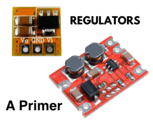
Types
Lets cover some basics here - voltage regulators are primarily defined by their output voltage and function:
Step-Up (aka Boost)
Just as the name implies, this type steps-up the voltage from a lower voltage to the specified regulator voltage. 3V, 3.3V, and 5V regulators will output 3V, 3.3V, and 5V respectively, but you don't want your supply voltage to be higher than the rated output of the regulator you’re using. Supply a 3V step-up with 5V and that’s likely to toast the board.
Step-Down (aka Buck)
Once again as the name implies this takes things down… if the console needs to run at 5V but there is 9V supplied, then you’d need a step-down to, well, step-down the voltage from 9V to 5V. To be honest, aside from some AC wall adapters, I cant think of any console that I’ve ever needed ‘just’ a step-down.
Step-Up/Step-Down (aka Buck/Boost)
This may be easier to wrap you head around, as it’s a combination of the step-up and step-down… this kind of board is what you want in a Game Boy DMG if you are needing one for your mods. For example if you want to power a backlight using a voltage regulator, you’re going to need a 5V step-up/step-down because the battery supply in the DMG can be up to 6V but also can drop below 5V… in this example so long as the input voltage is within the regulator’s range, it will simply supply 5V.Note:
- Output current: You’ll also want to pay attention to the output current too in order to know if the regulator can power your mod(s) properly. For example if a backlight takes 60mA but the regulator tops out at 50mA, it’s not going to work for you.
- Input range: Be sure to look for something that is capable of low voltages to cover your bases. For example there are some 5V step-ups that their low-end input is 2.5V… it doesn’t take long for the 3V in your Game Boy Color/Advance to get to 2.4V, at which point the 5V step-up will fail due to that voltage being out of range.
- Why not just use a step-up/step-down all the time? That’s a question I posed to Shawn not even all that long ago, and Shawn once again pulled out his saying of ‘there is no such thing as a free lunch’… so with the step-up/step-down capability to boost or buck voltage, the efficiency is lower… whereas the step-up only boosts the voltage, so typically I see efficiency ratings ~10% higher in just step-ups vs step-up/step-downs. Efficiency is just as it sounds - how productive it is with the electricity it’s drawing from the batteries.
Phew! That was a lot… but it’s all important stuff!
Ok… but why do I need it?
In the Game Boy Pocket, which I’m using this article as an example, there is a stock (built-in) regulator that will step-up the 3.0V [or less] voltage from the batteries to what the console needs, 5V. The regulator, though, can only handle so much current (mA) draw and was not designed for a backlight (for example). So when you backlight a Pocket and just tap into the stock 5V step-up voltage regulator you’re adding 5V and 60ma of ‘burden’ to the console which is out of range… if your Pocket will even start up, you will see the console display fading in and out trying to maintain 5V and your backlight will be very dim as it isn’t getting the current it needs. Not to mention that running mods off of the stock regulator will potentially overheat the stock regulator, shortening its lifespan.
How we alleviate this is using a 5V step-up (aka boost) wired to unregulated (aka battery) voltage on the console’s board. The notion here of unregulated voltage is an important one… if you were to use the console’s stock step-up as input for your supplemental regulator, it’s the same issue as the backlight… the regulator won’t get the current it needs. See the diagrams below for where to find unregulated voltage on some common consoles. Unregulated means it’s directly from the batteries and is before the step-up in the circuit.
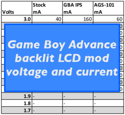
Another reason you might need it is a mod that works on a range of voltages, which again impacts current draw. When a mod takes a range of voltages, it will by nature have different current draw based on the source voltage.
Installation
This could be the part you’ve been waiting for all along… and while I was super intimidated by the notation of a voltage regulator, Shawn’s video demonstrated that it’s actually one of the easier mods to work with.
Input voltage - positive: Wire to the positive pin from the unregulated positive pin.
Output voltage: Wire to the positive end of your mod, such as the red wire on a backlight.
Ground: Wire the ground (-, black wire) from the mod to ground the voltage regulator, then wire the regulator’s ground to the negative/ground pin for unregulated voltage.
Here are some common consoles and where to find unregulated (aka battery) voltage:

Game Boy DMG

Game Boy Pocket

Game Boy Color

Game Boy Advance
Note:
I’ll spare you the details, but know that by introducing a supplemental voltage regulator to the system there is the potential for background noise added to the system, especially if the capacitors (aka caps) have not been changed. Good news is that we have capacitor kits directly from the experts in re-capping at Console5.
4 comments
Joseph Horvath
Hello there,
Im doing a gameboy advance build with your ips v2 screen, clean juice battery and board, and ill be overclocking with oscillators and switch. What kind (if any) voltage regulator would i be looking for?
Hello there,
Im doing a gameboy advance build with your ips v2 screen, clean juice battery and board, and ill be overclocking with oscillators and switch. What kind (if any) voltage regulator would i be looking for?
Ron
Hi, I installed the backlight to my GBP using Shawn’s video and also added the 5v regulator using these instructions.
Now when I’m using AC adapter only the backlight is lit. When I’m using batteries both the GBP and backlight work properly. Any ideas how to get the system powered using AC?
Hi, I installed the backlight to my GBP using Shawn’s video and also added the 5v regulator using these instructions.
Now when I’m using AC adapter only the backlight is lit. When I’m using batteries both the GBP and backlight work properly. Any ideas how to get the system powered using AC?
sjm4306
@ Andreas Markström pin 3 and the unreg pin- marked in the pic above are both ground and connected together in the circuit so attaching to either for the negative wire is perfectly fine
@ Andreas Markström pin 3 and the unreg pin- marked in the pic above are both ground and connected together in the circuit so attaching to either for the negative wire is perfectly fine
Andreas Markström
Hey. I Have a question about the negative wire cable routing on a GBP. I followed Shawns video. Step up booster NEG to pin 3 instead of the unreg. pin as in this guide. I have my backlight NEG directly to the unreg pin and not connected via the booster as in this guide. Would this have any importance? Performance wise or anything?
I do suspect my battery time is way to low after the mods. (testing atm.)Could this have a factor in that problem?
Regards Anree_GameBoy_Collector