Matt G, better known as linklooklisten, is a modder based in New York City, New York and a prolific poster on Instagram and Twitter. We became aware of him via his Instagram feed by not only the designs and photography, but also the helpfulness of helping people learning and do things is a 'breath of fresh air' as it were. He's keenly interested in helping build up this hobby.
He decided to take our recent post about adding a 5v step-up regulator to the Game Boy Pocket when backlit and kindly made a pictorial guide out of it and a video to showcase the different.
Simply enough, thank you Matt!
===== ====== =====

Ever since I received this Extreme Green Gameboy Pocket in the mail back in December of 2016, I wanted it to be more…extreme… more… green. And what better way to do that than by adding a green backlight to it. I had already modded a bunch of original Gameboy systems at this point and became familiar with AGS-101 screen mods for GBAs. This Extreme Green Pocket would be my first pocket to modify. I installed the backlight, slept that night, and installed the bivert module the next day using the V2 bivert which meant I had to run wires from the front of the motherboard to the speaker area where the bivert rested as well as a resistor to the backlight. It wasn’t easy since it was my first go at this, but I prevailed.
Now in 2019, much has changed in terms of boards and backlights. Biverts have shrunk, and resistors are built in to backlight ribbons. Since the times have changed, I figured to at least swap the older bivert for the new one and also add a 5v step-up regulator so that my first modded pocket can have a better 5v source to keep the backlight nice and bright. I’ve yet to install a V3 backlight because the V2 with a resistor gets the same results. Many flash carts like the El Cheapo and Everdrive can also cause the Pockets backlit screen to flicker when a rom is being written to it’s memory, contrast may be adjusted to undesired levels automatically or the screen could turn blank entirely. Installing the Pololu 5v Step-Up module fixes these issues as well.
Let’s begin!
What’s required:
- Y1 and Phillips screwdriver
- Soldering iron and supplies (a thin tip on the soldering iron is recommended)
- Wire
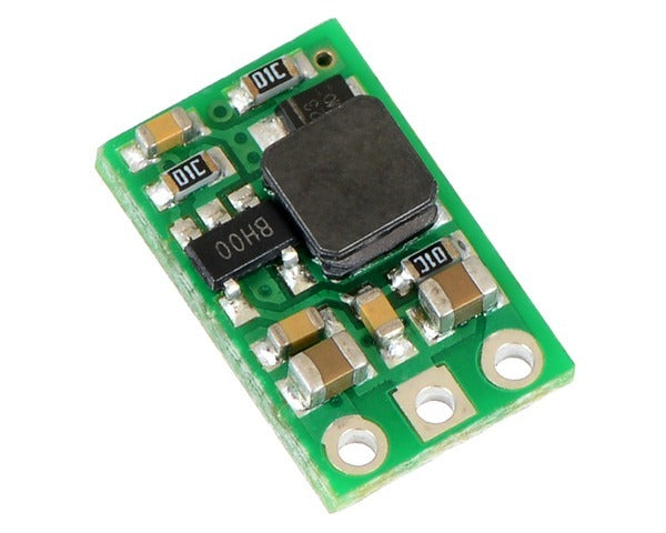
- A Pololu U1V10F5 (this is the 5v regulator, very small which is perfect for a Pocket)
- Patience and time (don’t rush!)
- Quick tip: always solder ground (GND) lines first!
First, open up the system. (I installed the drop-in bivert chip a few weeks ago.)

Focus on the lower right area on the board. We’re going to prep the 2 solder joints labeled 3 and 1. If you follow this to the front of the board, 3 connects to GND and 1 to VCC on the pockets DC regulator. Add some solder to both of these. I chose this spot instead of the speaker because the Pololu U1V10F5 is so small, it fits in this area with zero interference to wires, capacitors or the shell when attempting to close. Personally, I prefer to see little to no wires. Clean builds look better than spaghetti, but to each their own! If you dig wires, put more in there!

Next, prep the Pololu 5v regulator with some solder too.
Before:  After:
Next, I measured how short of a wire I’d need to cut to make VIN on this little board reach #1(VCC) on the back of the system board (VCC on the regulator), I did the same for GND on both the small 5v board to #3 (GND on the system regulator),
Connect GND on the 5v board to #3/GND on the system, then VIN on the small 5v board to #1/VCC on the system. Always solder ground first!
We’re good with this small board for now. Let’s shift gears to the backlight. Since this system was already modded, I had to remove the 2 wires on the backlight ribbon. I measured how long the new wires would need to be in order to reach GND and VOUT on the Pololu 5v board. Again, this is my preference. If you do not want exact measurements, cut longer wires. After measuring, I connected a blue wire to the - solder pad, and a red wire to the previously removed resistor, and connected the resistor to the + solder pad, with both wires facing to the left.

Slide the backlight back in to the display and carefully wrap the wires around to the front of the system board. Solder the other end of the blue wire to GND on the Pololu board and make sure the wire currently in GND stays in there.Then solder the red wire to VOUT. In the end, we have 2 really short wires connecting the Pololu 5v board to the Pocket system board, and the 2 backlight wires going to the Pololu board. I snuck in a piece of Kapton tape under the Pololu board as a safety precaution.

The red and blue backlight wires should fit perfectly between the system board and shell. This is another reason why I prefer wires at the exact length. If they were any longer, they would have to get tucked in a bit further and be visible from the front of the system. I guess this is more of a non-issue if you have a solid colored Pocket, but I’ve found myself still cutting wires to their exact length even on non-transparent systems for practice. I want them to look good inside of the system whether you can see it or not.

Upon closing the system, you’ll notice the back of the shell closes with no problems. Nothing gets stuck or is too snug. In this particular build, you can see the Pololu step-up board. If you want to, you can tape down the step-up board using a piece of double-sided tape, but the 2 wires being so short also means the board isn’t moving anywhere.

Put in 2 AAA batteries to test it all out. The result should be a brightly lit screen.

I keep trying to perfect this particular Gameboy Pocket, which is why it’s been a work in progress over the past few years. I cannot stress this next part enough: the drop-in bivert option is totally worth it and makes a massive difference in the quality. The contrast pops and overall image quality looks much cleaner.

As an alternative, the Pololu board could be installed on the back of the speaker, just trace the wire length along the bottom of the system board. That should keep things looking clean as well. Also, using a V3 backlight means no need for a resistor.
As I mentioned earlier,the 5v step-up module fixes flash cart loading issues. This video shows what it's like trying to load an Everdrive on a modded Pocket both with and without the Pololu 5v board installed.
About linklooklisten
Matt G (linklooklisten) is a regularly shared modder on our social pages (Facebook, Instagram) and we're glad to have him join us in sharing some articles with you about modding. He has always loved portable gaming and got his first limited edition gold colored Game Boy Pocket as a child and started collecting Game Boy games. He began modding Playstation Portables (PSPs) back in 2005, later installing different colored shells, custom firmware, creating what was known as Pandora batteries and making recovery memory sticks for friends and forum goers. Fast forward to 2016 when he would backlight his first DMG Game Boy and the rest is history.
Profile: linklooklisten


